Grand Touring Concepts is excited to share the experience and knowledge of fellow Lada enthusiast Nagy Emil! Please read on as he covers the principles of Lada Engine compression ratios and answers some common questions about the topic. Follow along with the 3rd part of the article!
(Part 1 of this article can be found here: TAKE ME TO PART 1)
It is crucial before taking the parts to the machine shop, to have a plan, and a desired camshaft chosen. Most of the camshafts have the specs well defined, and you can easily find the necessary CR value.
How to calculate the Compression Ratio
When doing the maths, you will need:
- Diameter of the bore, in centimeters (cm);
- Length of the stroke in centimeters (cm);
- Volume of the cylinder head combustion chamber (standard is 41.3 cc);
- Volume of the piston dome/recess (dish) for an exact calculation;
- Approximate thickness of the cylinder head gasket when compressed, with the bolts are tightened, (the volume added can easily be calculated);
Do not be intimidated by the formula below, we will walk you through the calculation process in the next few steps.

| VC = | Volume of the Cylinder |
| VHG = | Volume which is added by the Head Gasket thickness |
| VCOMB = | Volume of the Combustion Chamber |
The formula can be further refined if there are other volumes involved (valve recess, domed pistons)
Step 1 Calculate the Volume of the Cylinder
For example, we can take the original Lada 2103 engine data, where the bore is 76 mm, (7.6cm) the radius is ½ the diameter, in this case, 3.8cm, we will call this value (R).
The Stroke of this engine is 80mm (8.0cm) we will call this value (S).
The volume of the cylinder is π(pi)*Bore Radius (R)*Bore Radius (R)*Stroke (S), that is 3.14*3.8*3.8*8= 362.73 cc.
Step 2 Check the Volume of Cylinder Math
As a method of checking the correctness of the volume of cylinder we would simply multiply to check total engine cylinder displacement. Since this is a 4 cylinder engine we would multiply this number by 4 to calculate the entire engine displacement. 362.73 cc multiplied by 4, equals 1450 cc, close enough to the values from the book for this engine 1452 cc. The “missing” 2cc is accounted for in rounding errors, but is close enough for bench calculations.
Step 3 Calculate the Compression Ratio with the Numbers
For this example calculation we will assume the compressed head gasket is 1.8mm thick
Now we are getting somewhere, start with the Cylinder Volume as found above, 362.73 cc (VC), add (+) the Head Gasket Thickness 8.17cc (VHG), add (+) the Combustion Chamber Volume of 41.3 cc (VCOMB) = 412.2cc mark this number down and hold it as the numerator (top number) in this ratio.
Next we find the denominator (bottom number) in our ratio, 8.17cc (VHG) add (+) 41.3 cc (VCOMB) = 49.47cc
Finally we that the top number 412.2cc and divide (/) by the bottom number 49.47cc = 8.33:1
8.33:1 Compression Ratio compared to the original 8.5 the error is acceptable.
Recommended Modifications, Tips and Tricks
The biggest question and area of concern in a raised CR engine, is will the engine be able take the extra thermal and mechanical load, or will it cause long-term damage?
Cylinder Head Warp, and Combustion Chamber Failure
The first designs of Lada cylinder heads were intended for use with leaded petrol, and since leaded fuels can cause a lot of health and environment issues, these fuels were phased-out, and no longer can be found.
All of the old type cylinder heads have a “wall”, from the combustion chamber towards the manifolds, which is not supported from behind. There is a large cooling fluid pocket is located under it, that under bigger amounts of heat and load (mechanical, thermal) can warp. This is especially common when the head is skimmed to raise the CR, and the thickness of this wall is reduced as an unavoidable result of the skimming process.
Later “Made in CCCP heads” were revised to work with unleaded petrol, through the factory use of hardened valves and valve seats. In addition to revision for unleaded fuel, the head warping flaw was corrected, and the walls of the combustion chamber are fully supported. These heads can easily be identified, on most of them the part number no longer is cast, only the “sdelano v cccp” (Made in CCCP) is written on them.
Preventing Cylinder Head Warp and Supporting the Chamber Wall
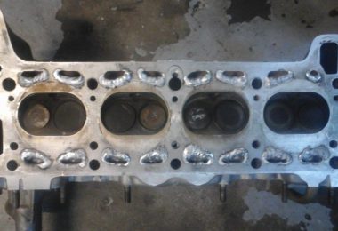
If you have a standard cylinder head this can be corrected by drilling a hole, thoroughly cleaning the channel that is located under it, and building a small re-enforcing wall by using TIG/MIG welding process.

Notice the welds marked with red that were done in order to support the combustion chamber wall on an early style cylinder head.
In my case, besides welding the support points, I modify the cooling passages. In the example below which has an oversized 84.5mm bore, Additional material is added to the cooling passages to maintain a adequate sealing surface between the cylinder and coolant line. Failure to do this modification to the coolant passages of the cylinder head when over boring the engine can result in premature head gasket failure with expensive results.

After the welding was done, the excess was milled off with a fly cutter, and the gasket surface prepared with a stone based resurfacing machine. The combustion chamber is factory machined quite well; the only improvement that could be done is to round the edges with a small radius after the final resurfacing to prevent detonation by overheating sharp edges.
Skimming the Head & Block, additional considerations
By skimming the head/or the engine block, you will create a slack in the camshaft timing chain, that cannot be removed with OEM parts. Only by using an adjustable camshaft sprocket will you be able to properly align the camshaft timing to the crankshaft TDP. Failure to do so, will place the camshaft off index, which will move the horsepower and torque peaks to undesirable points of the engine RPM range.

The adjustable camshaft sprocket, allows correct indexing of the camshaft after skimming the head or block
Also, the Adjustable Camshaft Sprocket is needed because the symmetry point of a modified camshaft differs from the symmetry point of the original, and the timing would be off, and also allows fine adjustments to be made easily. The simplest way to make a timing reference is to measure the valve lift at TDC (usually the manufacturer of the cam has these specs) with a dial gauge when the cylinder head is not yet fitted, and make a index mark between the camshaft and it’s aluminum housing. This is the reference, and from this mark you can fine tune the timing when the engine is assembled.
Head Gaskets
Another way to increase reliability is to use a metallic head gasket, compared to the basic OEM gasket the metallic gasket offers much improved durability. They are available for purchase, in Hungary, as full metallic construction, or you can save a little bit of money by using the newer version of Niva metallic head gasket. Either of those pieces will do the trick.
 In this photo you can easily notice severe OEM head gasket failure at multiple points. Observe the small separation surface between water lines/cylinder/cylinder head, this is the reason why I reduce the size by welding them up a little bit. This type of gasket material is unsuitable for High Compression ratios.
Pistons
Another tip is when you are raising the CR, is to use high quality pistons. I’ve had some bad experiences with FIAT 131 pistons, which severely failed. These pistons were not original, and were not a quality aftermarket piece (like Nural, Kolbenschmidt), so in little time because of the high CR, bigger thermal load, maybe detonations during spark advance, and timing setup, the ring lands failed.

 It is also necessary to mention that these pistons were modified, besides cutting the valve recesses, I cut down the lower part of the piston skirt, and machined the head of the piston. Fitting them a H beam rod is also a good matter of safety, and using the circlips to fit the pin is more practical than the original press fitted pin system.
Engine Cooling with High Compression
The cooling system actually can handle very well the extra stress (electric fan type cooling system), but a small upgrade to later types of radiators (slightly bigger in size, thermal switch located a little bit higher/closer to the cylinder head ) is always recommended. When fitting the new type radiator you will need to cut the upper pipe that runs between the cylinder head and radiator, and fit a middle piece (usually I use a piece of stainless steel pipe) because the length of the original hose is not long enough.
Ignition Timing and Control
Another important thing is to tune the ignition system, to prevent misfires, and avoid too much ignition advance. Detonation will quickly damage an engine and by increasing the Compression Ratio, it the risk of detonation is greater than at 8.5:1
Incorrect ignition advance can cause overheating, detonation, and low/high rpm incoherence. The ignition timing curve that is written on the original ignition module can work to a certain degree, but if you use a higher lift cam, and higher CR, the use of a programmable ignition controller is recommended. Some say that the VW Golf MK3 1.6 ignition module has a timing curve that complies better to many applications that use a higher CR and bigger lift cam.
Under any circumstances do not try to fit the VW module to the Lada ignition system, because the pinout of the VW module is different (although the plug fits perfectly), and also the VW Hall sensor is powered by 7 Volts, 8 Volts or 11 Volts, so the 5 Volts powered Lada sensor will burn out.
Points Ignition Warning
If you are still using points breaker ignition, it is necessary to upgrade the system to the OEM hall sensor based ignition system. This gives high end spark fidelity, higher reliability, as the old breaker is spring based, and at high RPM due to the spring’s elastic characteristics and vibrations, it will bounce off the cam, thus not giving ignition at the required moment. This could result engine pinging, which at high revs can lead to catastrophic piston failure.
Carburation and Fueling
The fueling system also should be adjusted. Better engine breathing, bigger vacuum caused by the higher CR/cam can easily alter the mixture quality, usually making the mixture leaner. To enrich the mixture you need bigger venturis (standard Lada carbs have 32mm-32mm or 28mm 34 mm setups, some can be altered), jets (alters the mixture from mid to high rpms), modified emulsion tubes (globally corrects the mixture), and somewhat bigger air corrector jets (these have a big influence on high end performance). Failure to properly adjust and correct fueling mixture will result in piston and valve damage, and this detail should not be missed.
In ideal cases, individual cylinder fueling would be the best solution; 40-45 Weber/Dellorto/Solex carbs can easily do the trick. For street use, 40 mm carburetors are more than enough, but be advised that there is no standard application for jetting them, cams/CR/engine capacity can easily affect the jetting, and it’s more of a trial and error setting them up. The most helpful tool in this process is an AFR (Air to Fuel Ratio) gauge kit, which analyses the exhaust gases with a lambda (Wideband) probe.
Camshafts and Valvetrain
Since one of the main goals of increasing Compression Ratio is the support the use of “Big” Camshafts, therefore it would be incomplete to not discuss aspects of the valvetrain. Always before fitting a camshaft, check its specifications and try to make a mock-up mount, to avoid surprises like the one in the picture below:

Valve spring bind is no small problem, when it occurs the results are never good.
In this situation you should consider using special springs, these could be found at http://www.schrick.com/, http://catcams.co.uk/.
If it’s out of the budget, you can try to fit VW Golf MK 3 GTI (ABF, KR, PL ) valve springs, some will be a direct fit, plug and play (also consider using the valve retainers), others may need certain modifications on the valve retainers (the conical hole needs to be bored, the cone has a different specifications, and the cotters of the Lada valve will not go inside the retainer all the way).
In Part 4, Emil will cover common combinations and wrap up the topic!
Is the lada 1.5 cylinder head different from the 1.6 or 2101?
How much HP could I expect with a 1.5L vaz engine with 4age individual throttle bodies,ported head,lightem valves,msd ignition,10.5 compression,lightened flywheel and 272 cam(i am not sure if the car is actually cammed..but from research it appears to be). I used this forum to aided me in the building process of the engine
Is the cylinder head of the 1.5 lada engine different from that of the 1.6 or 2101?
Is the clylinder head of the 1.5 lada engine different from that of the 1.6 or 2101?
no, all older heads are the same, only the newer 1700 has reinforcements in place. 1700 heads come in two variants with manual set valves and hydraulic ones…older ones can be “mixed and matched”…1200,1500,1600 and older 1700
lada samara (front wheel drive) has different head, as well as 1300cc lada engine, both with cam belt, instead of chain.
hope this helps…