This article is supplemental information to our extremely popular video on debunking the myths around the 1994/95 Mustang Constant Control Relay Module. If you haven’t yet watched it, it is highly recommended viewing before beginning diagnosis or spending cash on parts replacement.

It can be found here:
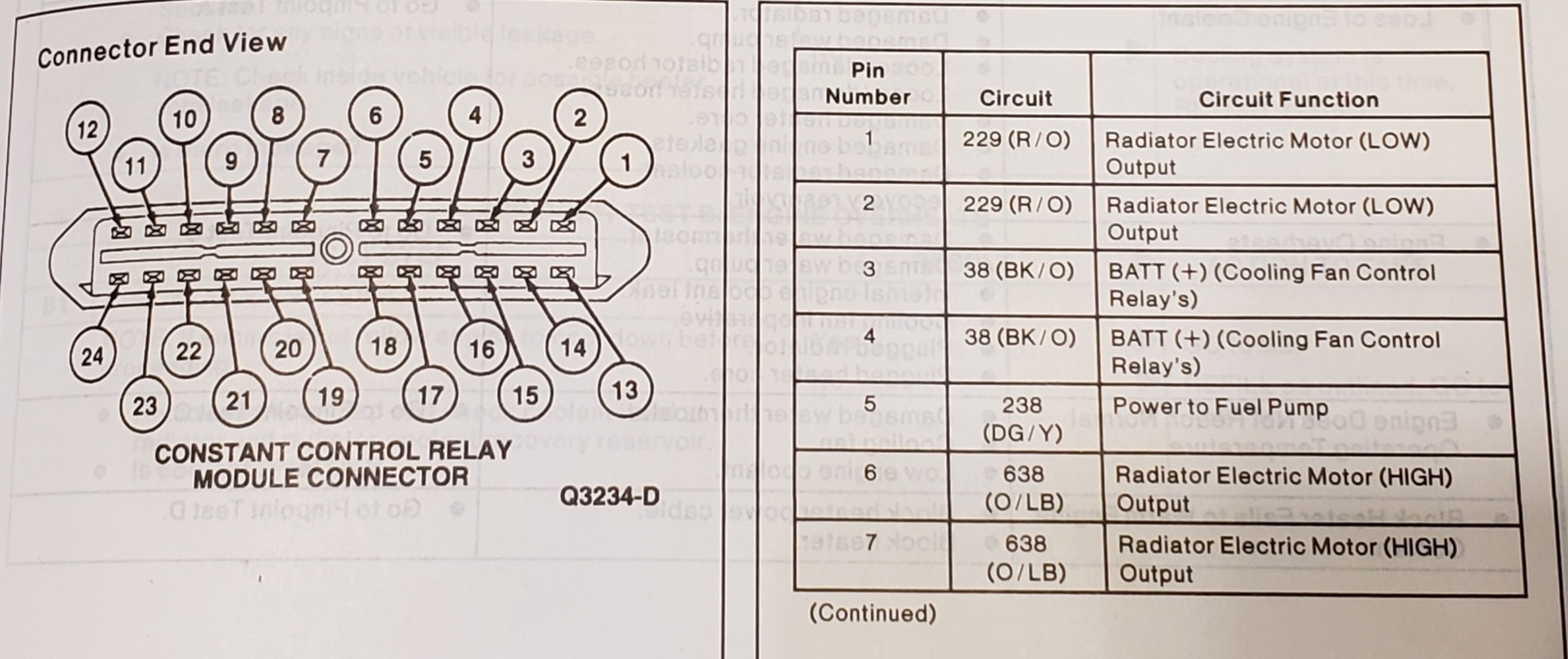
If you have watched the video and feel your problem is still related to the CCRM, and you would like to investigate, we have sourced these pin-out diagrams and diagnostic procedures from a 1994 Mustang OEM manual. These have been a frequent request from our viewers and will fully walk you through verifying the that CCRM is good.
Remember the CCRM only controls the engine cooling fan, A/C, and the fuel pump. If you have Hi/Lo engine cooling fan, which is easily checked by using a jumper wire in the OBD 1 port to begin a code read sequence, your CCRM fan relays are fine. The Fans are trigger at both Low speed and High speed during that OBD readiness check.
If you cycle the key to the RUN position, hear the fuel pump prime (buzzing from the rear of the car) and have pressure at the fuel rail, the Fuel Relay in the CCRM is fine. Since the 94/95 Mustang is a return style fuel system, the pump runs at full voltage at all times (12V) and pressure is regulated by a vacuum actuated bypass into a return line.
Any ignition break up, shuddering during acceleration, random stalling, poor power, raw fuel smell from the exhaust, etc. indicate problems with other systems, and are not related to the CCRM. We are really passionate about this at GTC, as the internet continues to spread the myth, and many resellers of junkyard parts are continuing to profit from this trend, and do nothing to solve the issues with your Mustang.


Below is the only test in the entire manual which involves the CCRM:
PINPOINT TEST F: Engine Cooling Fan Does Not Operate When A/C is Activated (1994 Mustang Manual Page 12-00-27)
F1 Check Voltage Supply to Cooling Fan:
- Start Engine and run until normal operating temperature is achieved.
- Turn Engine OFF, leave ignition switch in RUN position.
- Actuate A/C damper door switch to MAX A/C position.
- Using a test lamp, check Pin 1 Circuit 229 (R/O) and Pin 2 Circuit 229 (R/O) for voltage.
Did the test lamp illuminate?
Yes – GO to F2
No – Skip to F3
F2 Check Cooling Fan Ground:
- Using and ohmmeter connected to a known good ground, connect second lead to black ground circuit at cooling fan motor connector.
Is the resistance 5 ohms or less??
Yes – Skip to F5
No – Service fan motor ground circuit for open circuit. Retest Vehicle from F1.
F3 Check Voltage Supply to Constant Control Relay Module (CCRM):
- Using a test lamp, check Pin 3 Circuit 38 (BK/O) for voltage.
Did the test lamp illuminate?
Yes – Skip to F5
No – GO to F4
F4 Check Fuse (60A):
- Using a test lamp, check both sides of the fuse (60A).
Is the fuse OK?
Yes – Service Circuit 38 (BK/O) for open circuit. Retest Vehicle from F1.
No – Service Circuit 38 (BK/O) for short circuit. Retest Vehicle from F1.
F5 Check Cooling Fan Motor:
- Disconnect cooling fan motor.
- Using a No.10 Gauge wire, connect one end to battery positive, Connect other end to cooling fan, low terminal at fan motor.
Did the cooling fan run?
Yes – Service Circuit 229 (R/O) for open circuit. Retest Vehicle from F1.
No – Replace Cooling Fan Retest Vehicle from F1.
END OF PINPOINT TEST F
If you found this helpful, consider dropping us a line on Facebook https://www.facebook.com/grandtouringconcepts/ or better yet, subscribe to our youtube channel: https://www.youtube.com/channel/UCUpmR1ydr6OQ8LrccIARSPg?view_as=subscriber
Thank you for your video! I’m in need of the anatomy of my 99 Mustang’s CCRM. I want to run diagnostics on it. Below is a link to a 96 CCRM schematic and bench test steps. My CCRM schematic is just a tad bit different – enough to look for my specific CCRM. Any help would be great! The compressor clutch is not engaging, even after replacing the CCRM. As you stated, they rarely go bad. One guy on YouTube just replaced the AC relay on the CCRM by removing the rivets you described and soldering on a new one. I decided to just replace the whole CCRM from LMR with a “Blue Streak” brand made in China. I want to bench test the old one. I will also “jump start” the clutch to see if it engages as well. Any help would be most appreciative! Thanks!